Photos of Mechanical, Front Panel Design
Portable electronic instruments. These photos show knobs, nuts, knurled, and know-how (Pete’s). These are working photos of our differential amplifier project. They show how we can get the electrical boards to line up with the mechanical connectors, and controls. And how an extra layer of plexi can be used to add a nice finish, and provide a solution to the incompatible height of the controls (note the nut is recessed by the plexi).

Overall view of assembly, showing how it slides into the case
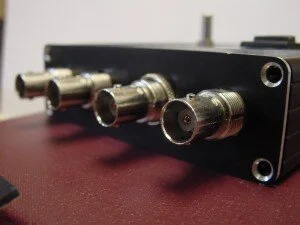
Close up of the BNC connectors

BNC aignment of pcb, fron panel, and mounting BNC panel
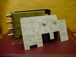
Cardboard pcb mock-up, with the real board and assembly behind it - we like to make quick mock ups as we design, just to check everything is going well
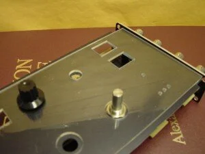
Detail of the plexi layer used to 'bury' the nut needed to hold the front panel control. The plexi is an additional part, but the incompatible heights of the controls meant there had to be some way to accomodate all these part variations.